This article gives an overview of the main steps taken by a customer to rebuild a three-bearing Ruby engine. The engine is for a relatively light special, based on a completely rotted-out Ruby. The aspiration is to build a reliable engine producing approximately 21bhp for road use. The aim is to show the key steps taken and any modifications which were made. The completed motor will be tested on a dynamometer to ascertain the power of the finished engine.
This article is not intended to be a full guide to building an engine. There are a number of other such websites covering this, including a comprehensive write-up on the Dorset Austin Seven website http://www.da7c.co.uk/technical_torque_articles/austin_seven_engine_rebuild%20(hereford%20A7C).html
Photographs
There is a gallery of photographs for the rebuild at the end of the article.
The Starting Point
The engine was a runner and although it had no untoward noises, it was severely lacking in power. It was decided to fully strip and rebuild it.
The Head
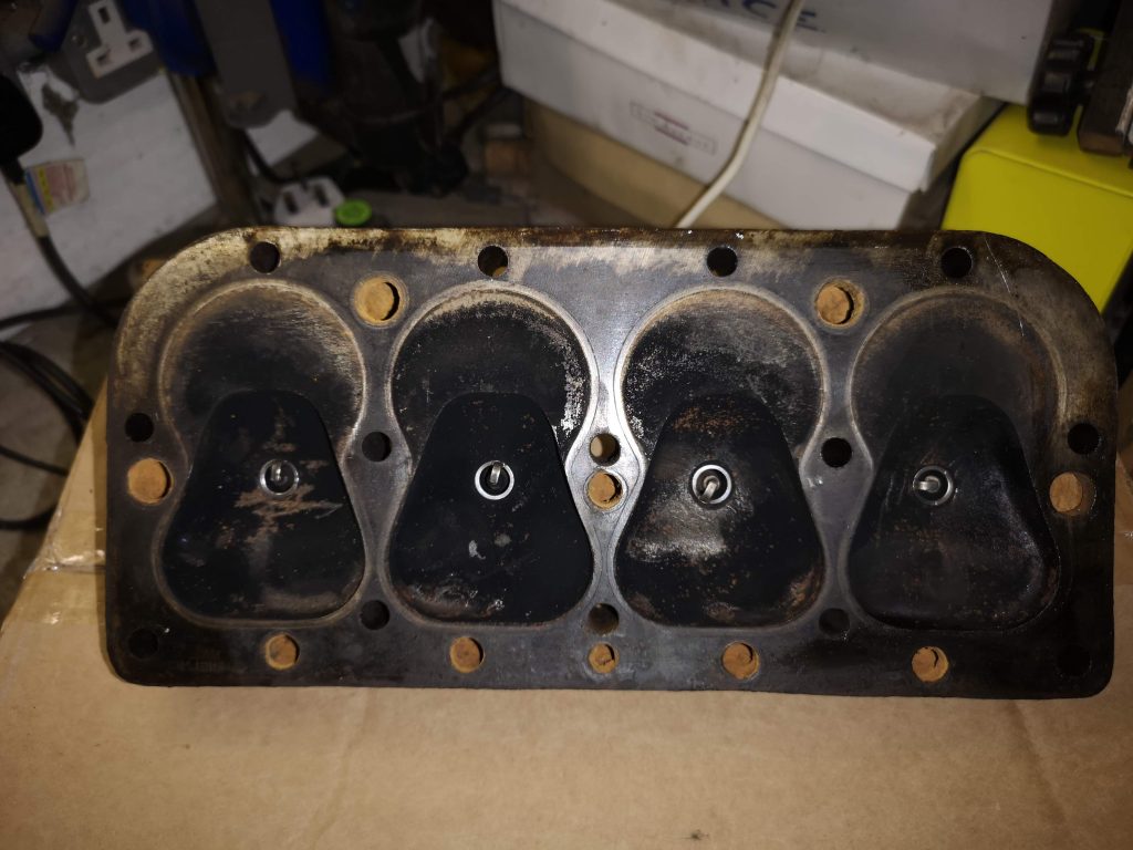
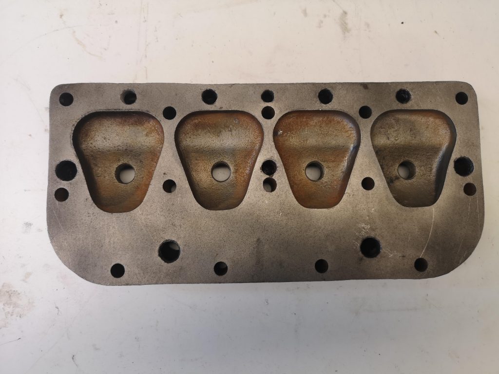
The head is a standard high compression Ruby head. When it was removed, it was apparent that the gasket had been leaking between the middle two cylinders. The head was sent away to be acid-dipped to clean the water ways and blasted to remove the old paint and grime. It was then given a light skim to ensure that it was flat, as was the mating face for the water manifold. The core plugs were removed and the seats carefully cleaned with a scraper and a Dremel. All of the passage ways were flushed out with a hose pipe and, when thoroughly dry, blasted through with an air-line to remove any residual debris from the water ways. For obvious reasons, this was done outside.
Finally, the core plugs were replaced, seating on a bed of Hylomar gasket sealant, and the lot painted with Halford’s satin black VHT paint. Care was taken to ensure that the surfaces underneath the head washers were kept clear of paint to prevent the possibility of the paint compressing over time and contributing to potential leaks.
The Block and Valve Gear
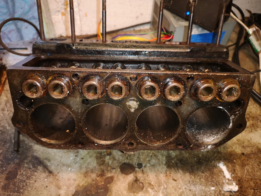
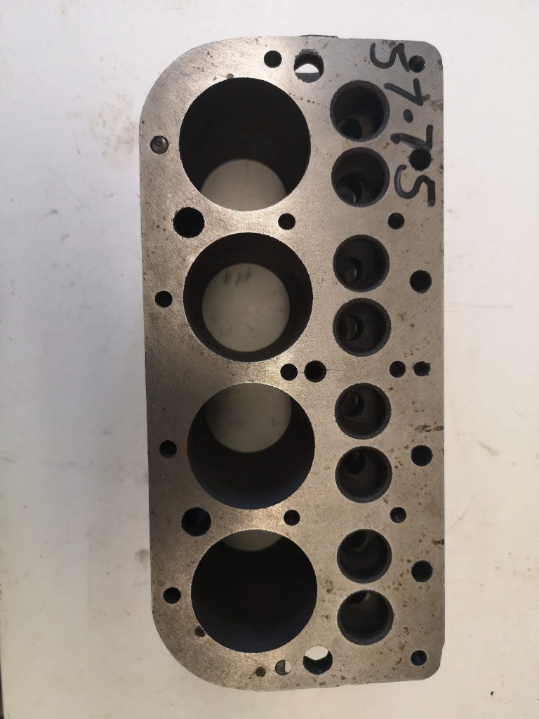
Once stripped of everything, the block was sent to be acid dipped and blasted to remove any rust and to clear all of the water and oil ways of blockages and sludge. Afterwards, it was sent to be honed and the surfaces faced. The bores had been fitted with liners at some stage. Sadly, a light hone revealed that the bores were badly pitted, right through the liners into the main block, necessitating new liners. This was too expensive and a replacement block was found. This time, the block was successfully bored out to 58mm, all mating and gasket faces skimmed to ensure that they were flat and the valve seats were recut. All threads were checked and those few which were weak or stripped were helicoiled.
The valve guides were replaced and reamed after being shortened in the lathe. The portion which usually protrudes into the port was turned away to leave a tiny lip; just enough to retain a drop of oil to lubricate the stem on starting. This modification increases the ffective size of the port. The valves were all replaced. Although they were all in good condition, the existing valves had over-sized stems of differing diameters, meaning that each valve guide would have needed boring and reaming to a unique size. Replacing them with standard valves was more efficient and cheaper. The cam followers were replaced with re-profiled followers.
Finally, all of the waterways were given a final blast with the airline to remove any lingering debris, new core plugs fitted and the finished block painted black.
Modifications to the Block and Valve Gear
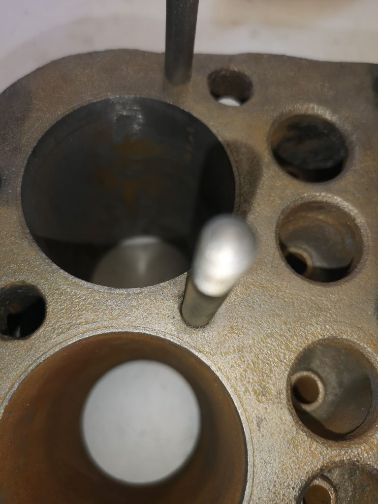
The inlet passages and ports were cleaned carefully to remove any protruberances and lumps; any corners and edges were given a gentle radius and the overall size of the passages was enlarged. The openings to the inlet ports were carefully matched to the corresponding opening in the inlet manifold to minimise disturbances to the gas flow. The ends of the head studs which threaded through into the ports were also ground away flush with the casting. All of the work was completed with a basic US Pro die grinder and a cheap pencil die grinder, both powered by a small compressor.
The cam followers were replaced by a set which had been re-profiled and flattened, but with the edges gently rounded to prevent them from hitting the cam with undue abruptness.
The valve guides were shortened in the lathe to minimise the length that protruded into the ports.
The ends of any studs which threaded through into the waterways were drilled away to ensure maximise waterflow.
Once the bottom end of the engine is finished and the block and pistons have been reassembled, the edges of the cylinders opposite the valves will be relieved to aid flow.
Camshaft
The inlet lobes have been gently reprofiled, with approximately 0.006″ being removed from the rear, or “flat” side of the cam. This should give a moderate boost to performance, making the most of the improved carburtettor and porting, but without rendering the engine intractable.
Crankshaft, Flywheel and Clutch
The crankshaft was crack tested and then balanced. The flywheel was lightened and then balanced on the crankshaft. The pivot points on the clutch fingers were replaced and the working faces all smoothed and cleaned and set to the correct height.
To lighten the clutch pedal when in use, small rollers were placed next to the fulcrum point of the lifting levers. This reduced the pressure needed to lift the clutch when it was on the bench, so all being well, it should make the pedal lighter too. Other than new friction material, nothing else was done to these parts.
Crankshaft: Centre Main Bearing
The three-bearing engine has a reputation for breaking their crankshafts due to poor alignment of the centre main bearing. What is reported to happen is that on some engines, the centre bearing housing in the crankcase is at a different height to the other two. Consequently, when the centre bearing is tightened down, it bends the crankshaft slightly, putting it under stress. Luckily, this engine appears to be satisfactory. A dial gauge was used to measure the deflection of the crankshaft as the centre main was tightened, and Plastigauge was used to check for clearances. This was repeated a few times to check for consistency. There was no more that 0.001″ deflection and the Plastigauge showed the clearances to be within tolerances. Rotating the crankshaft showed no tight spots. There is extensive literature on the internet about this, including the “Speedex” modification, if the crankshaft shows an unacceptable amount of deflection when being tightened. Engine building lube was applied liberally to the bearing shells.
Ancillaries
Healthy ancillaries are just as important to the efficient running of the engine as the mechanics themselves.
Distributor
The distributor is a standard Lucas DK4 automatic advance unit. After being dismantled, everything was cleaned in the ultrasonic cleaner. All moving parts were checked carefully for excessive wear and any burrs on the bob weights, the base plate and the cam were dressed to ensure that they did not stick. There was a little play in the shaft which was would have affected the consistency of the points gap, so replacement “old stock” bushes were fitted and reamed to remove all radial slop. Shims were fitted to minimise vertical play. A new drive pinion was purchased, but was found to be just soft steel: it was case-hardened before being fitted. The moving parts were lightly lubricated and the unit reassembled with new points, condensor, rotor arm and cap.
Carburettor
There was no carburettor on the engine when purchased, so an 1 1/4″ HS2 SU was bought from e-Bay. The device was stripped completely and everything was cleaned using an ultrasonic cleaner. It was just a cheap, basic unit from Lidl, but it is surprisingly effective.
After being cleaned, the carburettor was refurbished with a black jet, a blue spring and a number six needle. The butterfly throttle valve spindle was replaced because it was worn, although, oddly, the holes in the body where it rotates were unworn. The mounting flange was checked to ensure that it was flat and not distorted. It was rubbed down on a sheet of wet and dry paper on a flat surface to remove any burrs and high spots. Everything was thoroughly cleaned and the needle carefully centred in the jet so that the dashpot plunger rose and fell smoothly. Finally, a brass-topped damper was fitted, purely for cosmetic reasons.
Inlet Manifold
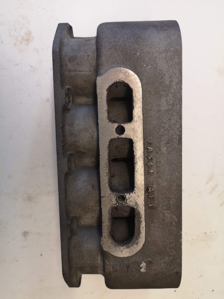
An aluminium John Barlow inlet manifold, suited for the SU carburettor, was fitted. The inlet port profiles were gently adjusted to minimise any step between the manifold and the port.
Exhaust Manifold
A second-hand, welded tube, four-into-one “bunch of bananas” manifold was obtained. Again, the ports on the engine were matched as well as possible to the manifold ports.
Dynamo
This appeared to be a hybrid of models, but was in reasonable condition. The coils and armature were tested for continuity and short circuits, the commutator cleaned, the brushes and bearings replaced and the device was painted and reassembled. The terminal block was missing, so a replacement “new old stock” item was fitted. It was tested on a battery and “motored” smoothly: turning it from a drill produced a small voltage, as expected.
Starter Motor
This had good, healthy kick when tested with a battery, so it was cleaned, any service items replaced, a new pinion retaining spring fitted and the unit was reassembled after painting. The contacts in the starter switch were filed and burnished to ensure that they were flat and gave a good contact. The pivot on the arm was also checked to ensure that it moved freely.
Testing
The engine was tested on a dynamometer to ensure that it ran and to measure the power output. The modifications proved to be successful and the engine was found to be producing in the region of 21bvhp.
Next Steps
All that is left to do now is to finish building the car in which the engine is to be installed. A lick of paint, Mr. Fawlty.